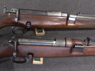
This rifle came to light prior to the Rock Island Premier Auction in September of 2013, and sparked some interesting discussion amongst Ross collectors…

I had the chance to take a look at the gun firsthand at RIA, and filmed a brief bit of video of it:
Since I wasn’t able to disassemble the gun, I was a bit limited in what I could find out at the time. However, after finding some additional photos taken when the consignor had disassembled the rifle, we are able to see a bit more. The mention of this rifle in The Ross Rifle Story (by Roger Phillips) consists of this:
The self-opening phenomenon exploited by Blish was investigated during the development of General Thompson’s submachine gun ans was incorporated in the Model P. The firearm, an autorifle, was developed by Oscar V. Payne and Theodore H. Eickhoff, in Cleveland, Ohio and was tested in 1920 at the Springfield Armoury, where it set a record for reliability for such rifles in the 5,000 round test.
An interesting feature about all this was that when Thompson began experimenting with the Blish principle (starting with US Patent 1,340,943, filed November 26 1917) he found it would not work with high velocity rifles. This problem however, was overcome when Payne and Eickhoff modified a 1910 action Ross rifle to attain a true and successful Blish application. Reference to this is found in US Patent number 1,247,576, wherein rotation is accompanied and facilitated by a drop in pressure.
This explanation has some errors in it, as the patent listed as a modified Ross is actually for a cigar vending machine. Payne and Eickhoff were the core employees of the Auto-Ordnance company (which was General Thompson’s firm, established to build the Thompson Auto-Rifle and later the Thompson SMG), and do not appear to have had any relationship with Sir Charles Ross or the Ross factory. In addition, the Thompson rifle never set any such reliability record – in fact its unreliability was noted in testing reports from the time. If Payne and Eickhoff ever actually did experiment with a Ross rifle, it is not this one. While this rifle has a Ross magazine, barrel, and furniture, its action incorporates no Ross parts and it has no mechanical similarity to the Ross.
As a straight-pull bolt action rifle, the Ross is in many ways ideal for experimental conversion to semiauto, since a gas piston need only push straight back on the bolt handle to open the action (unlike the more common turnbolt rifles, which would require a camming action to translate gas piston travel into rotary motion). This type of conversion is precisely what Joseph Huot built as the Huot Automatic Rifle. The Blish system, however, does not utilize locking lugs in the same way as a bolt action, and there would not have been much reason to use a Ross action as a testbed to modify.
Ultimately, we have no verifiable knowledge of who built this rifle. The poor fit of the wooden parts and the lack of markings tends to suggest against it being made at the Ross factory, and there is no real evidence to suggest that it was made by Auto-Ordnance. It is certainly a unique piece, and I suspect it was made by an enterprising firearms designer who never managed to make it fully functional. Over time its history became hazy, to the point that all we can do today is try to analyze its parts and guess at its story.
Here are additional photos of the gun for your perusal (small ones taken from the RossRifle.com discussion forum and the really big ones from Rock Island Auctions):
For what it’s worth, the winning bidder at auction spent $11,500 to become the new owner of this rifle.


Interesting piece, ambidextrous layout seemingly – swivelling cocking handle, ejects upwards.
The brass “blish” locking piece seems to be very upright if you will, sort of immovable it’s shape isn’t at an obtuse angle i.e. If you pushed the bolt against it, how would it move. You have to physically push it down to cock the piece, so I don’t understand how any metallic resistance properties the blish principle would alter this. I don’t think the Tommy guns application of this system was designed in that manner, you could cycle the action without depressing something.
Does a piece move inside the bolt, what is the smaller of the two pieces on the fully stripped receiver photo it’s narrower end resembles that which protrudes from the rear of the bolt on the bolt removed photo.
The brass piece appears to have a hole on it’s lower edge, on the magazine with stock removed photo. Maybe the entire piece folds to the rear presumably, hinged like. After it is depressed initially, by some method…
GAH! FIDDLY! What person makes a redundant safety that doesn’t work in battle?
The cut out for the brass pieces hinge, or “depressing” rod is angled actually.
Whole arrangement – lock block and its supporting rod with spring appears to lean some 5deg forward. I try to trace logic behind it; it would appear more logical if it had a ‘negative rake’ meaning angled the other way. However, what also comes into it is geometry of surfaces between breech and the block which is not visible. But as Ian says, it yielded too violent extraction anyway and that rendered idea useless.
The stock seems far away from the trigger, do you think it was an purely experimental piece a working model “that didn’t work really”
Yes Ian, that would be my take. And that is what Ian McC. says in video. At the same time, I feel due respect to creators of this experiment, no doubt.
A prototype d’oh.
Yes it is great it’s survived, living history.
It actually has quite nice lines, kinda attractive. I think it would have been quite sleek… Could have been, once they sorted out making it work etc.
On the underside view, I noticed that the action tang is not inletted into the stock, and in fact is square, not even being contoured. Not only does this pretty well indicate that the rifle is a “tool-room” job, but I wouldn’t be surprised if it drew blood if the rifle had any amount of “kick”.
As for the Blish lock not being well adapted to high-pressure loads, a Gun Digest annual a few years back had an article about prototype Thompsons made in various calibers for commercial potential and U.S. Army trials before and during WW2.
Besides obvious calibers like .38 Super Auto, 9x19mm, and .22 LR (no, really), prototypes were also built in .32 WSL, .351 WSL, .30 Carbine, and one in .30-06(!) The latter was intended as a “stop-gap” SAW due to production of BARs not meeting the demand, so to speak. That one had a buffer tube assembly that stuck out 6″ behind the receiver.
While most of these were non-starters (although the .38, 9mm, and .22 were interesting), I think it’s a shame that at lest the .30 Carbine, or better yet the .351 WSL, weren’t proceeded with. In .351, or a bottlenecked .351/.30 round, the Thompson could have been a forerunner of, and an “answer” to, the German MKb42/MP43/StG44 series. Like the Russian Federov “Avtomat” of 1915, an early version of the assault rifle.
cheers
eon
One of those strayed directions in firearm development. Not to be awfully critical, but see the sharp corner at spot where the stress is high since the portion between chamber and block tends to stretch, at front of lock well. And back side is rounded as it should be; oh well…
This Blish thing, as much as novelty at its time, ended up in nothing – just to prove that there is no need for it. It ought to be learning case to purveyors of unorthodox solutions.
Thanks for bringing this up.
An impressive amount of machine work to do in pursuit of what looks to be (with almost 100 years of hindsight)an unworkable idea. It’s wonderful that it has survived. Most failed inventions or even successful prototypes end up in the scrap pile.
Blish principle aside, has anyone any ideas how you would best use it’s layout to incorporate a workable mechanism?
I would pin a bar inside the receiver running from its rear lower end running diagonally to the top of the locking pieces spring, remove the locking piece and split the bars end to fit over the spring/guide rod.
The bar would be pinned in a hinged manner, so it could move. The bolts lower rear edge would rest on the bars front which would be cut to fit. The bar could be pressed down against the spring, allowing the bolt to move rearward as it would now be clear of the bar.
A bolt carrier would be attached to a bolt by it’s guide rails fitting into recesses on the carrier, and would move independently from it upon recoil.
The carrier would be attached to the bar via two flat plates either side of it pinned through both parts in a hinged manner.
The recoil spring would sit behind the bolt, upon firing the bolt would be locked by the bar untill the carrier moves rearward, in so doing the attached plates impart pressure on the bar via them swivelling downwards.
The carrier stops at this point and the bolt moves rearwards through the carrier, the bars upper front end being compressed beneath it. The bolt returns and the bar springs upwards forcing the carrier forward via the plates, the bolt is now locked.
Well that’s better than my first attempt!
Good idea but it may be iffy to put trust into spring to push up the brace (lock) and to keep it there reliably. In some way this in similar as (bracing swing bar) was applied on Mannlicher 1905 semi-auto with the exception that was controlled by recoiling barrel and extension. Nifty linkage but too many members.
By the way I think there is just one piece breech with requisite utilities (firing pin, extractor) not carrier&bolt as we are used to from gas operated guns.
Speaking of springs, it is useful to distinguish the types we have now (coiled and flat of constant section) and those used on guns up to roughly end of 19 century. Those were purposely designed low performance (low stress) formed in appropriate way. They would outlast any other part in the gun. Time is gone on those.
Perhaps Denny hard to tell if the bolt is separate…
I should have put my glasses on : ) still it’s been interesting looking into the Blish lock and generally going off on a wayward tangent.
The comment by the author quoted in the article says “Reference to this is found in US Patent number 1,247,576, wherein rotation is accompanied and facilitated by a drop in pressure.” rotation, I wonder if that is something to do with that circular piece behind the locking block… Or the cigar machine.
“Rotation” referred to the rotating breach block of a large-caliber naval gun, which is how Commander Blish discovered his principle.
I wonder what those circular devices are…
I’m still of the opinion that this was a gunsmith/machinist’s project to make a repeating rifle. He probably just cannibalized a inexpensive surplus Ross for parts.
Someone thinks it has some provenance to pay $11,500 for it… Maybe it isn’t supposed to be a Blish lock, the brass piece was just because it was a prototype and the designer was still scratching their head trying different things so they used a brass piece in order to be able to try different shapes more easily.
Some sort of primer actuated mechanism, to do with that cylindrical tube with the three screws in it that sits behind the locking piece. The force imparted by the firing pin, acts on it.
Perhaps there’s a sort of clock spring inside it, and it spins this lowers the locking piece… Bolt passes, returns, piece lifts via taught spring.
Or not…
If you fired that gun with the piece up, would it not be locked i.e. the bolt wouldn’t pass it so what lowers it?
Mysterious design.
Ian, et.al. I have a VHS from 1995 produced by one Clark E Hodges (Rim Fire Productions out of New Port Ricky, FL) on the Thopmsom SMG, in association with the William Douglas Museum which, among other things, shows a tool room model of the TSMG in .30-06 caliber…I don’t know if any copies of the VHS are extant or even available at this time, but I transferred mine to DVD format a few years ago…If you’re interested I could loan my copy (VHS or DVD)…the similarities are intriguing!!!
CB in FL
I’m British Chris old old bean probably be considered terrorism here old videos of gun workings but thank you all the same, Tsmg hmmm. I was looking at the top of the barrel on the fully stripped receiver picture there is a ramp section with a hole it, and on the bolt removed picture there’s a rod protruding from the front upper side of the bolt which looks to fit inside it.
Some sort of direct impingement, from the chamber.
If the separate piece on the fully stripped receiver is the bolt then it appears to be separate from the carrier so it could move against the return spring while the bolt was still behind the locking piece. What lowers it though…
Interesting information…I think you meant to say “New Port Richey”, which is 35 miles north of Tampa, FL.
Yeah…RicHey…NOT RicKey!!! I a friend who used to live there….two of my Army buds live in Tampa.
CB in FL
Certainly NOT the England of Alfred the Great any longer….or of Queen Victoria, unfortunately
“As a straight-pull bolt action rifle, the Ross is in many ways ideal for experimental conversion to semiauto”
It is possible to convert straight-pull rifle to semi-auto, but it wasn’t good enough for military use. For example: Yasnikov semi-auto rifle:
http://www.hungariae.com/Mann95Ru.htm
I would hate to see some schlemiel actually fire that thing! If the designer hadn’t thought up the pistol grip and rear sight, the user would have lost an eye! Anyways, that awkward Mannlicher conversion seems to be an intellectual exercise just like the “Ross” above. I suppose the Blish-lock Ross would be better for guys stationed in guard towers after a better action has been made for it…
Anyone want to hypothesize potential uses for this gun?
My money’s on a straight infantry rifle. after all, this was from the decades of the Bang, Pedersen, Hatcher, ZH-29, etc. There was even a Thompson rifle design. (I don’t recall offhand if it used the Blish lock or something entirely different.)
Most armies recognized the advantages of autoloading rifles for their infantry; the bottleneck was a lack of designs that were inexpensive to make, sturdy, reliable, and simple in mechanism. John C. Garand hit all of the “power points” with his M1 design, but Melvin Johnson came very close with his recoil-operated rifle and LMG.
If this is in fact the Payne/Eickhoff rifle tested at Springfield in 1920 (and I see little doubt that it is), that would have been part of the first round of Army tests that later included all the rifles I mentioned above, and finally culminated in the adoption of the Garand in 1935-36.
I’d call it a piece of U.S. Army Ordnance history, on that count.
cheers
eon
“John C. Garand hit all of the “power points” with his M1 design”
The U.S.Army during the WW2 was armed with semiauto rifles and therefore was unique.
But the main reason for this wasn’t the Garand but safe geographic location. Other nations in 1930s have also ready semiauto rifles designs but they have not enough time to produce it and completely replace the bolt-action rifles.
For example:
Poland – Maroszek wz. 38M – small batch produced.
France – MAS-40 later developed into MAS-49
Soviet Union – SVT-38 and SVT-40 rifles
Oddly, the “add a gas piston to a straight-pull and you would have a semi-auto” thing occurred to me while looking at a K31 a good while back. Anyone know if the Swiss ever experimented along this line?
“Anyone know if the Swiss ever experimented along this line?”
Rychiger designed the semiauto version of Schmidt-Rubin, but it was recoil-operated:
Short description: https://www.forgottenweapons.com/m1-garand-development/swiss-rychiger-rifle/
Rychiger patent: http://www.google.com/patents?id=rcMZAAAAEBAJ&pg=PA6&lpg=PA6&dq=rychiger+rifle&source=bl&ots=cithT9EYAh&sig=BJeVKJbrMNn_mW2FdcUhzwmPhIo&hl=en&ei=BAVFTNW4Esrdngee_aW_Cw&sa=X&oi=book_result&ct=result&resnum=10&ved=0CCsQ6AEwCTgK#v=onepage&q&f=false